

John Deere 90-Series ARRO® Installation Guide
ShieldAg Alternate Rotary Rowcrop Option (ARRO®) offer a range of advantages. Originally developed as a corn head conversion, ARRO® provides equally superior cutting ability when harvesting sunflowers, millet, milo, and industrial row crop hemp. Using the ARRO® corn head conversion system ensures the reliability of late-model corn head, reducing maintenance costs and downtime. We have kits available for multiple corn heads across brands and sizes.
This blog will focus on the installation process of the 90-Series ARRO® kit that fits John Deere 40-Series combine headers and John Deere 1293 combine headers built prior to SN 670751.
Let’s get started!
Supplies

Here is a list of the tools and supplies you’ll need to install your ARRO® kit:
· A ladder, platform, or step stool for working around the corn head
· Air compressor
· A source of electricity for power tools
· Electric or air powered impact wrench
· JD450 Deere special tool (Long puller) to remove stalk rolls / snapping rolls –Shield number SA450, re-designed to work for Deere 612C stalk rolls
· 4” wide putty knife for removing dirt and rust
· Allen wrench set
· 1-1/8” ½” drive impact socket for stalk roll puller, with break-over bar or heavy ratchet
· Dead blow hammer or sledge to knock on stalk rolls to loosen them
· 2’ long (or longer) air spout to blow dirt off of the gear cases and clean off the row units
· 15mm ½” drive impact socket for gear case bolts and to reinstall ARRO® cover plates
· 2’ long ½” drive impact extension to remove the gear case bolts
· Center punch or 3/16” drill for the drill template, 3/8” twist drill for 3/8” holes
· 11R Vice Grips to hold the drill template in place
· Small Mag-Base Drill and 11/16” diameter, 16mm OR 21/32” diameter, hole cutting drill (Hougen-style cutter)
· 12LC Vice Grip Brand Lobster claw vice grips to help hold the mag drill base on the thin sheet metal decks, if required
· 18mm ½” drive impact socket for removing and re-installing two forward latch/chain guide 12mm bolts
· ½” Female to 3/8” Male impact adapter, for removing grease plugs from gear boxes
· 15/16” impact socket and ½” drive wiggle tail to re-adjust chain tighteners, long bolt is 5/8-11
· 15/16” wrench to re-adjust chain tighteners, nuts are 5/8-11, not metric
· Another 15/16” impact socket and wrench OR 24mm socket and wrench for ARRO® disc 16mm bolt/nut
o Two sets needed because someone will be installing ARRO® Discs while another person is tightening the gathering chain adjusters
· 150 lb-ft torque wrench for ARRO® discs
· RTV silicone (large tube) to make gaskets for gear case covers
· Moly grease gun grease
· Drill lube for the Mag-Base Drill
· Blue Loctite for ARRO® disc bolts (recommended) and flat head screws holding discs to sprockets
· 2 gallons of corn head gear case lube or Deere polyurea corn head grease (use OE recommended lube), and small funnel to refill lost gear lube in each gear box—there is a dipstick on each filler plug
The Installation Process
1.
Start by cleaning the corn head with a power washer then an air blower to remove all refuse, specifically from the stalk roll drive gear box area. For safety and to ensure the easiest access, securely mount the corn head to the combine with lift cylinder safety blocks installed. Alternatively, you could mount the corn head on a secure combine header trailer but make sure you have access to all rows. The ability to tilt the header will allow for easier installation. Most work will be done at waist level.

2.
Remove chain guides, gathering chains, tensioners, deck plates, trash knives, and all hardware from the decks. Note that if your header has had modification for wear life in the throat of the deck, any large bars or heavy hard metal passes must be removed or accommodated for proper placement of the drill template. The drill template slides up into the throat indicated below, to assure proper placement of the sprocket disc assemblies. Mark chain tensioners with paint stick for re-use on the same rows.

3.
Inspect all gathering chains for wear. If the “droop” is more than two to three inches, the link pins have excessive wear (consult your header service manual), order new gathering chains as needed.
4.
Remove stalk rolls and cast housings (binoculars). Number each row with a paint stick for future re-use as a corn head.


5.
Re-use existing hardware and gasket along with silicone gasket maker to install the cover plate provided in the ARRO® kit. If your gear case lube was lost while installing new cover plate, replace it, as necessary. There is a hex plug on the top of each gear case for checking and filling gear lube.
6.
Clean any rust and scale off the top of the deck plates to prepare for drill work and installation.


7.
Place the drill template at the rear of the row unit frame as shown, making sure it fits against the actual throat of the row unit. Secure all components with a vice grip.
8.
Using either a center punch or a 3/16” pilot drill, mark or drill the four hole locations shown with the provided template.

9.
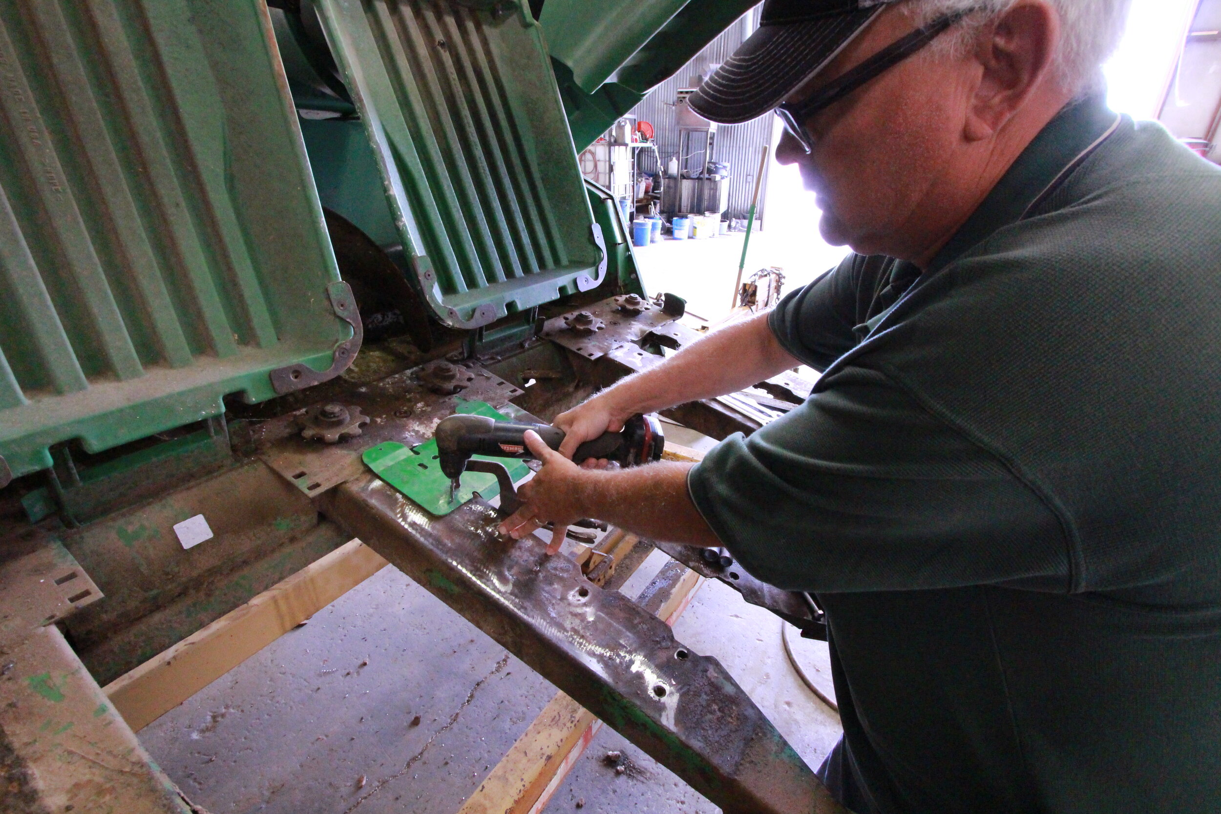
Drill the two rear holes (nearest to the hinge points) with a 3/8” diameter drill. A mag-based drill works the best for this operation.
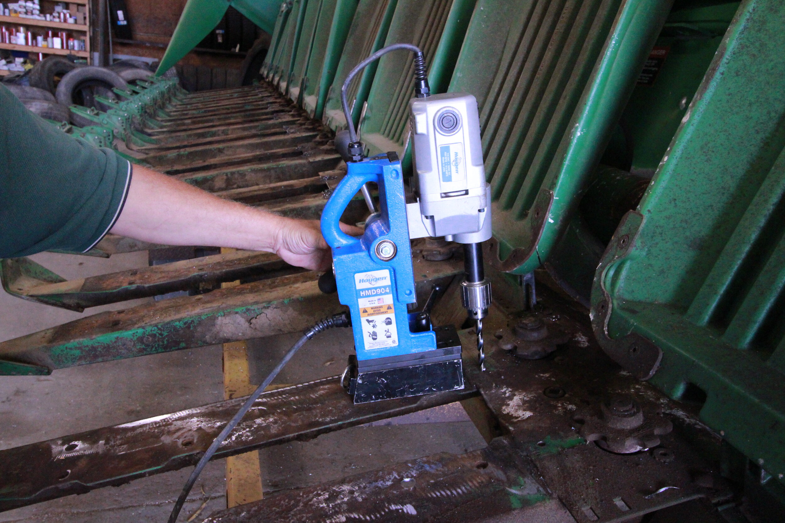

10.
Drill the two front holes (furthest from the hinge points) with a 16mm or 11/16” diameter drill. We highly recommend using a mag-based drill for this pair of precision holes.
11.
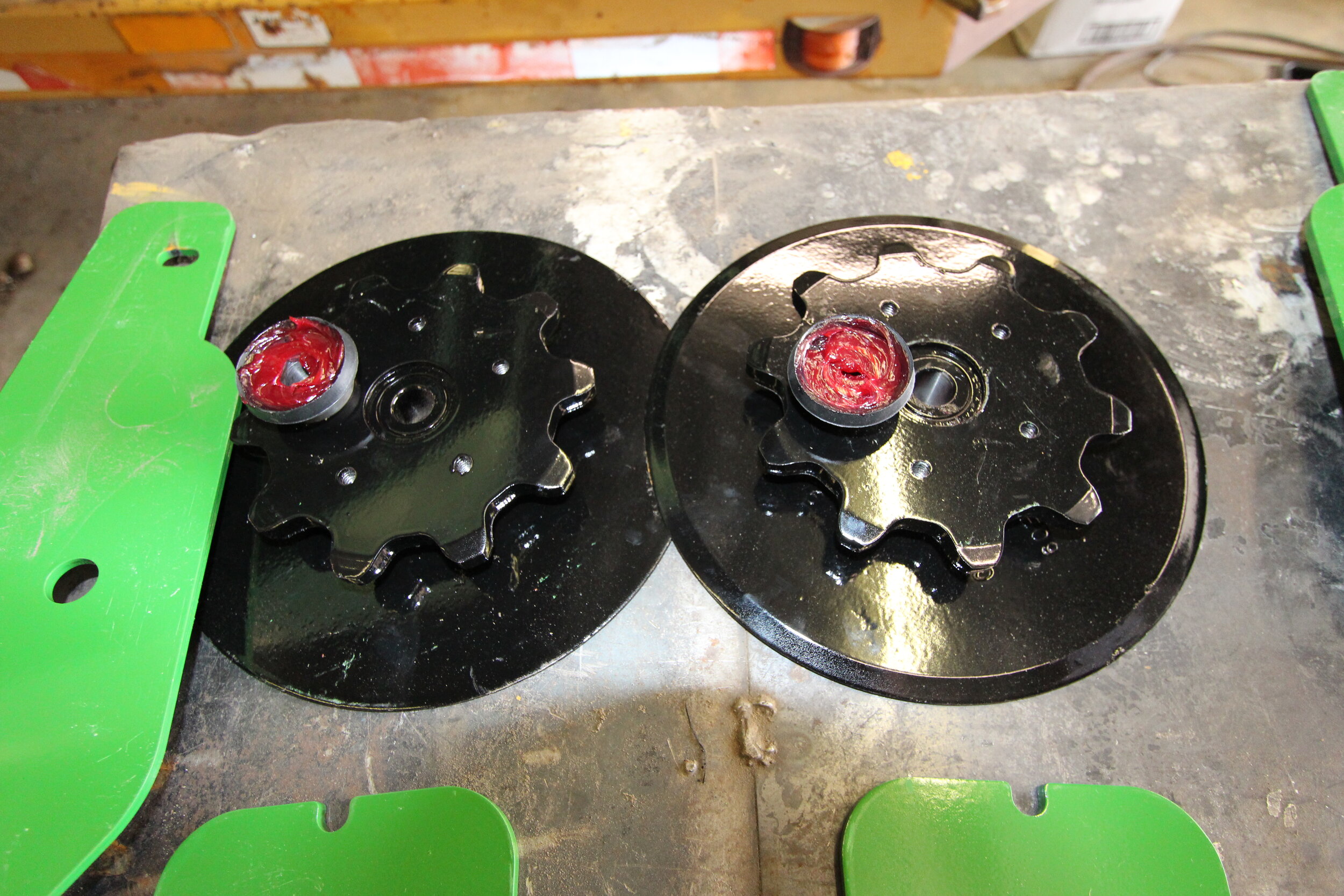
Lay out the two sprockets and add grease-gun or corn head grease to the small recess in the top of the sprockets.
a. NOTE: the parts diagram shows the orientation and placement of the matching pair of sprocket assemblies.
b. AT THIS TIME, please check the flat head screws that fix the discs to the sprockets with the appropriate tool (either Hex-Allen wrench or Torx). Make sure that the screws are tightened to 18-25 ft.-lbs.
12.
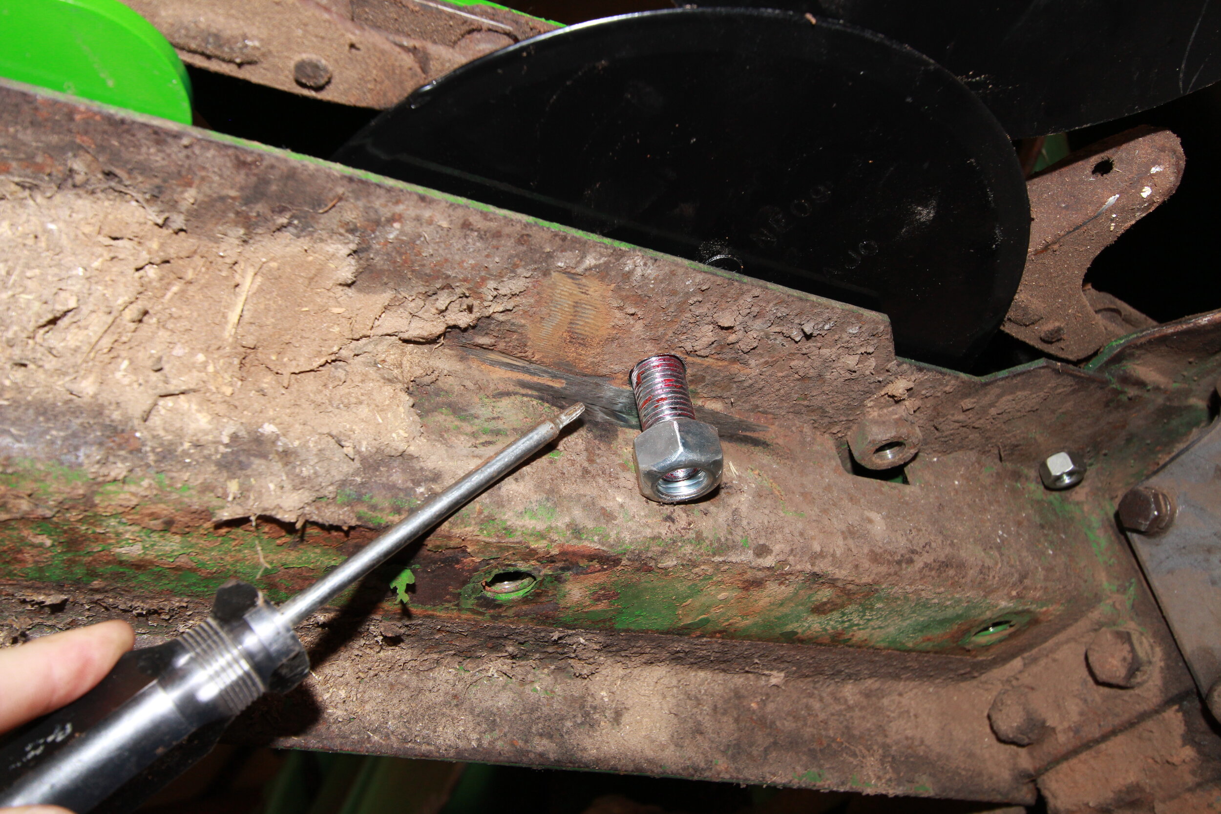
Check below the two 16mm holes, on the underside of the deck plates. If the drill work is near one of the stitch welds shown in the image, use a grinder and grind enough weld away so that the nut can set flat against the underside of the deck plate.
13.
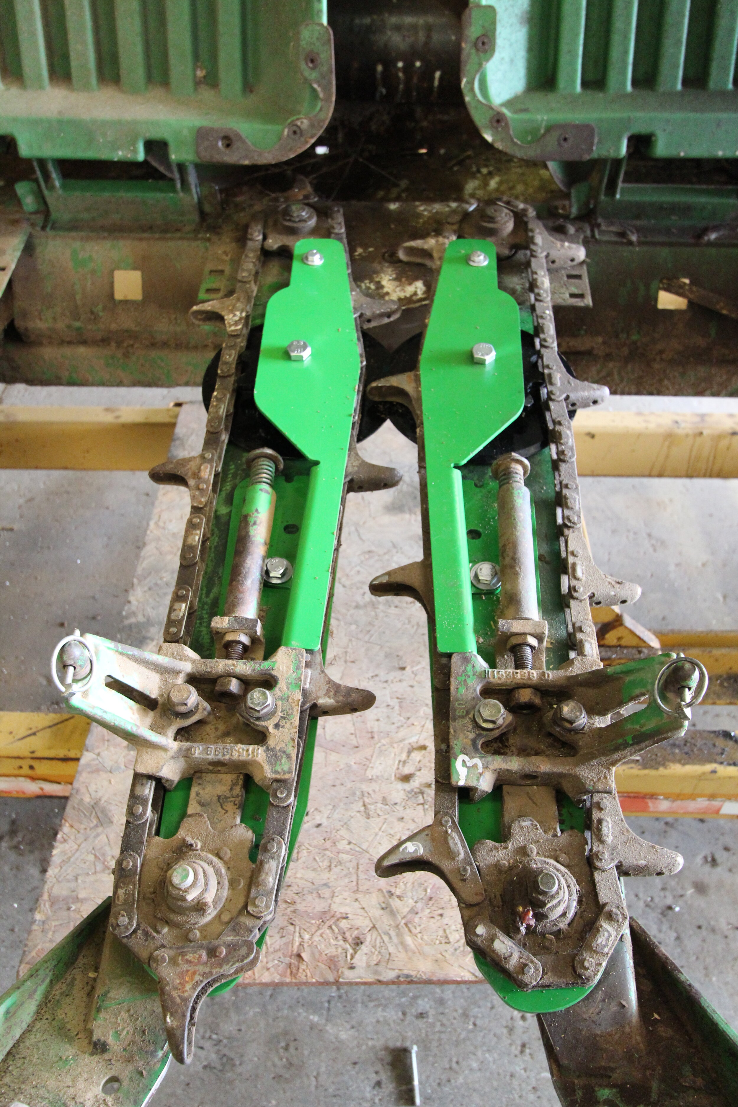
Lay out the two ARRO® deck plates as shown.


14.
Loosely install the 16mm bolt through the chain guide, special bushing, and rubber disc cap, through the disc assembly and install the shim or shims on the bottom side. See the parts diagram for proper orientation of the discs and shims.
15.
Install the chain guides with discs as shown, and loosely install all hardware.
a. Test-tighten the 16mm large hex bolts holding the discs down. The discs should turn reasonably hard against each other but not lock up. Turning one disc should force the other disc to turn. Change shim arrangements as needed to make the discs turn with good scissor action, but ALWAYS have at least one shim under each disc so that the discs are not sitting directly on top of the decks. Torque 16mm bolts to 150 ft.-lbs.


16.
Reinstall the chain guide tensioner assemblies then tighten all hardware.
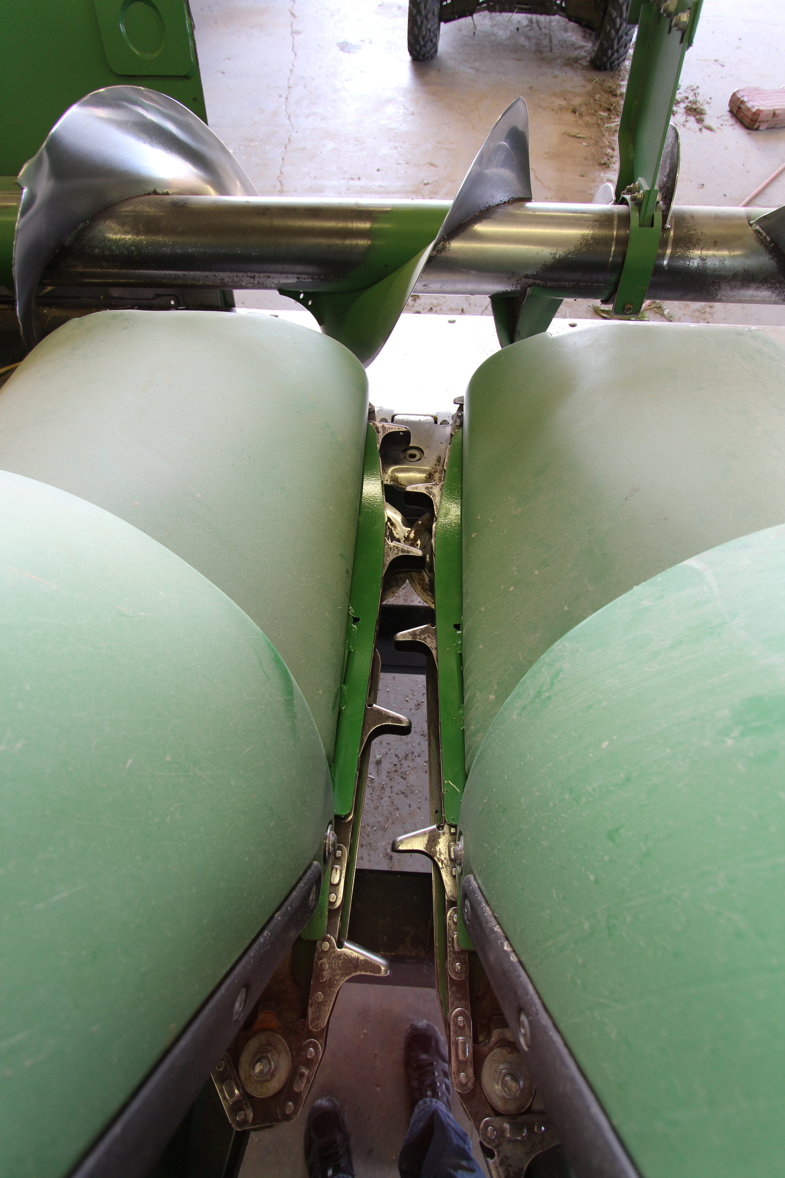
17.
Install the gathering chains, noting that the “lugs” must be staggered evenly, then tighten pre-load springs per the combine header service manual specifications, leaving an approximately 1/8” to 1/4” gap at the adjusting bolt head.
18.
Check that all tools and parts are removed from header and auger trough. Start the combine and run the header slowly and check for excessive noise, which is usually caused by worn out gathering chains.
19.
We recommend that you take the combine on a short round in the field, then shut off machine, pull up all snouts and check to make sure gathering chains are tight and the rotating discs are warm, but not hot, to the touch.
20.
Re-shim discs if they are running hot or there is too much gap between any pair of discs. The chain guides are designed to minimize bunching of stalks and leaves, but the ARRO® installation should be checked at least once daily during use.
Your ARRO® is installed and ready. Now the fun begins! You can harvest quickly and efficiently, leaving 12-15” of stalk in your fields that holds snow, fights wind erosion, and works as cattle feed.
If have a John Deere 600C-Series early model 8-tooth combine (link to that installation blog), John Deere 600C-Series late model 6-tooth combine (link to that installation blog), or a CaseIH 22-2400-Series/ 32-3400-Series/ NH 98C-Series combine (link to that installation blog), we have helpful blogs for installing ARRO® kits on those too!
Call (800)798-1968 for more information!